structural engineering companies in india

Things to Know About Structural Drawings

The first thing required for the development of structural framework of the building by design and construction professionals, are structural drawings. For the actual development of structural framework of the building, engineering solutions such as structural steel detailing structural drafting services, precast detailing, rebar detailing, and structural design services such as structural modeling and analysis are enormously essential. When it comes to the development of highly strong structure, structural detailing & drafting are the prime necessities.

During preconstruction, many different types of Structural Drawings are created by construction & design professionals which comprise structural shop/fabrication drawings, chimney drawings, structural connection drawings & erection drawings etc. Throughout the structural drafting process, all these drawings are generated by trained drafters with the close collaboration of structural engineers who keep on directing them. Other technical and highly important drawings which are also made during structural drafting contain roof, truss & joint drawings & foundation plan drawings etc. When it comes to the design & construction of structural framework, the role of structural drafters and detailers cannot be overlooked by engineers, architects, fabricators and contractors etc. They are solely answerable for the detailed development of fabrication drawings, erection drawings detailed technical plans and reports etc., when it comes to the importance of structural detailers.

All types of structural drawings, whether developed by detailers or drafters, must be revised, observed and approved by structural engineers before they are finally optimized by design and construction professionals for the actual development of structural framework.

Fabrication drawings and erection drawings must be made with extreme accuracy among all the above mentioned structural drawings, since they are optimized by design and construction professionals for extremely severe purposes which consist of manufacturing of structural parts & their eventual installation. Quality of those drawings can never ever be negotiated which are utilized by fabricators for manufacturing steel components as it can disturb the entire project very harmfully. Hence drawings formed for the optimization of manufacturers and steel erectors must be studied with high attention by structural services engineers so that no difficulties are confronted by them.

Visit Us: StrucCore

Fabrication Drawings

We bridge the gap between Design and Fabrication

What are Fabrication Drawings?

As compared to Manufacturing Drawings, fabrication drawings are generally used for 1 off’s or per job/project bases.

400px-Portal-1

They are manly used in:

  1. Sheet Metal
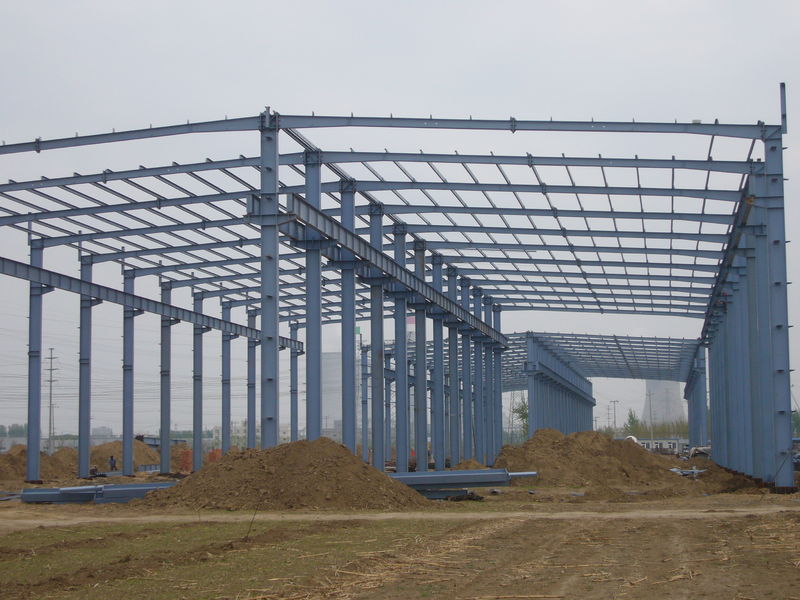
  2. Structural Steel
  3. Ballustrading/Handrails
  4. Stairs
  5. Architectural Steelwork

t-pic11

pl2665044-steel_structure_industrial_shed (1)

Manufacturing Drawings are split into 2 types:

1. Part Drawing

These drawings point the part itself that require fabrication for use e.g. by the welder. They also indicate the material and surface finish.

The drawings should comprise the following material. (On the other hand, they should not display further information than is required.) :

  • Linear Dimensions including Tolerances
  • Material Specification
  • Flat patterns including bend lines
  • Weld Location & Type
  • Weight
  • Angular Dimensions including Tolerance

2. Assembly Drawing

As per the complexity, Assembly drawing are often classified into a Top Level Assembly & Sub-Assemblies. This is to give more precision for the full product. Assembly drawings should comprise:

  • All parts to be fabricated
  • All Sub-Assemblies used within the assembly
  • Fixings such as Nuts, Bolts, Washers etc.
  • All bought in parts comprising their specific part numbers, supplier or manufacturer
  • Cut Lists stating angles & length
  • Bill of materials (BOM) showing a full list of all parts
  • The drawings should be shown in a way to obviously show how the Fabrication fits together. This should/could contain several views (Top, Plan, Side, Isometric etc.) & Exploded Views
  • Additional information that might be essential such as Weight, assembly instructions should also be included if needed.

It is significant that good quality drawings show all the information that is required, but no more than needed. An example is to many dimensions or to many views.


What Fabrication Drawings do we offer?

Struccore offers complete set of Fabrication Drawings for wide range of industries. We believe that in order to produce good quality fabrication that will aid an excellent installation on site a certain amount of coordination is required between all parties involved.

We are used to synchronizing with architects, structural engineers and steel manufacturers to create General Assembly Drawings & the subsequent detailed drawings showing connections, holes etc.

Our service prides itself in working closely with all parties involved to ensure any queries get raised and answered prior to fabrication commences.

What information is needed to create Fabrication Drawings?

It depends on the industry involved.

For Structural Steel Fabrication Drawings (including, Ballustrading, Stairs, Architectural Steelwork etc.) we generally work from the Structural Engineers Line Drawings in combination with the Architectural Drawings. We would normally visit site to check any potential clashes.


How much do Fabrication Drawings cost?

All are Fabrication Drawings are usually quoted on a fixed price basis as we are normally able to quantify the work easily. All we need is the Structural Engineering Drawings or Architectural Drawings in order to provide a fixed price.

TMTshapes

PREPARATION OF BAR BENDING SCHEDULE

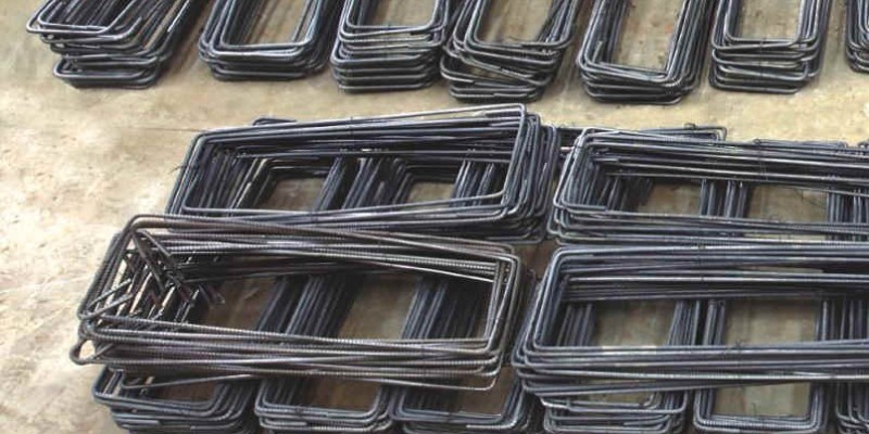
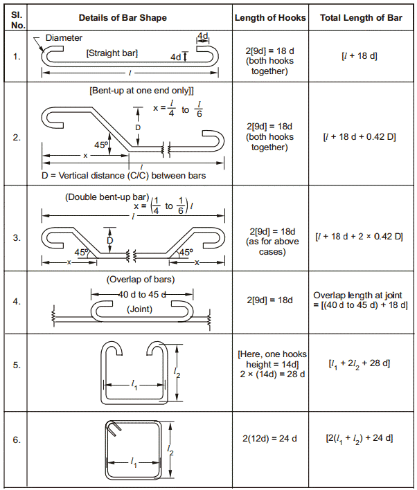
Schedule of bars (or bar bending schedule) is a list of reinforcement bars, with regard to a known RCC work item, and is offered in a tabular format for easy visual reference. This table sums up all the required specifics of bars as diameter, length of each bent, a total length of each bar, a shape of bending & straight portions, number of each type of bar and angles of bending. This statistics is a great benefit for preparing an estimate of quantities.

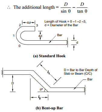
Figure 1 depicts the shape and proportions of hooks and bends in the reinforcement bars these have adhered to the standard proportions:

(a) Length of one hook = (4d) + [(4d+ d)]  where, (4d+ d) denotes to the curved portion = 9d.

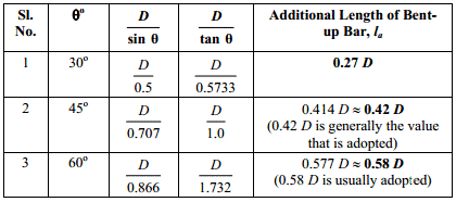
(b) The additional length (la) that is presented in the simple, straight end-to-end length of a reinforcement bar due to being bent up at say 30o to 60o, but it is generally 45o) = l1 l2= la

Where,

formula1

formula2

Fig 1: Hooks and bends in Reinforcement

Giving different values to respectively), we get different values of la, as shown below:

formula3

Figure 2 shows the technique to reach the length of hooks & the total length of a given steel reinforcement.

formula4

Fig: Typical Bar Bending Schedule


louvre-pyramid_1

Amazing Uses of Glass in Architecture

Selgas Cano Architecture Office

Selgas-Cano-Architecture-Office-by-Iwan-Baan-3

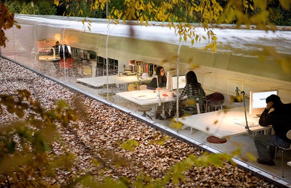
In the middle of a quiet Spanish forest, the Selgas Cano Architecture Office is a glass shell of creativeness.  The ceiling and outer wall of the office is entirely open to the nature surrounding it, due to a clear curved wall of glass.  All through the 4 seasons, the employees for Selgas Cano are directly in sync with environment.

Sears Tower Glass Balconies

sears-tower-glass-balcony_1

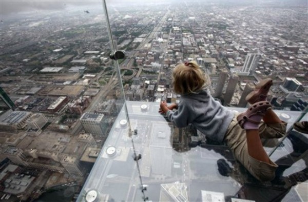
A hint of glass buildings can add a fresh new perception and a whole lot of fear to the already rising heights of the Sears Tower (also known as the Willis Tower).  The Sears Tower Glass Balconies range from near the building’s top at 1,353 feet.  The sight from the Sears is a matchless way of seeing the city of Chicago. They’ve added a new aspect to the Sears Skydeck experience.

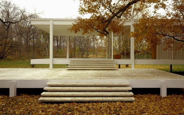
Farnsworth House by Mies van der Rohe

farnsworth-house_1

Being one of the modern period’s most eminent works of glass architecture, the Farnsworth House is a piece that pushed the envelope in the usage of glass in architecture.  The home sorts floor-to-ceiling glass all through, giving an open connection to the riverbank nature of the plot.

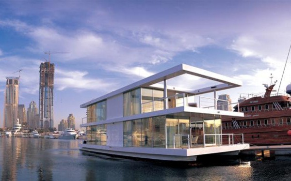
Glass Houseboat by X-Architects

Houseboat-by-X-Architects-1

The Glass Houseboat takes an obvious encouragement from the Farnsworth House, this time taking the white-beam-and-glass tactic to a sea-faring residence.  This expansive houseboat sports two levels on a pair of pontoons, skinned with floor-to-ceiling glass building in each direction.  Its residents are delighted with unbarred sights of city and sea, the ultimate mobile domicile off the coast of Dubai.

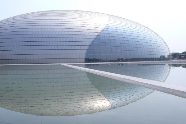
National Grand Theatre of China

National-Grand-Theater-of-China-1

The National Grand Theatre of China is a huge dome of titanium and glass, it is also one of greatest architectural works of China’s in last decade.  Located near Tiananmen Square, this glass structure stocks a theatre, an opera & a music hall, joining to seat 5,452 guests at a time.  The dome is focused within an artificial lake, offering a reflective sight of the dome from the lane.

Basque Health Department Headquarters of Bilbao Spain

Basque-Health-Department-Headquarters-of-Bilbao-Spain

Bilbao, Spain has developed as an architectural hot spot due to the Guggenheim Museum, Bilbao, by Frank Gehry.  While Gehry designed his masterpiece with metal, Coll-Barreu crafted the Basque Health Dept. Headquarters in angular glass with an almost organically-inspired shape. This building is easily amongst the world’s most progressive in form, when it comes to glass in architecture.

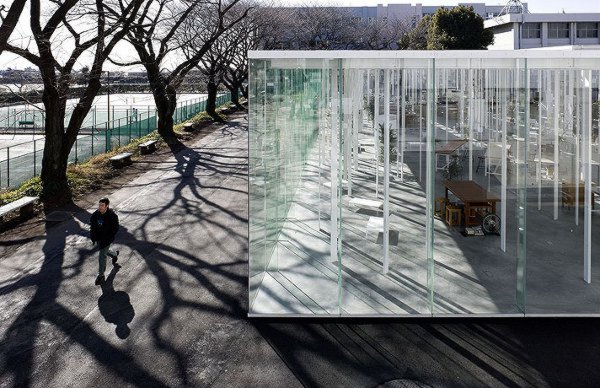
Kanagawa Institute of Technology Glass Building

Kanagawa-Institute-of-Technology-Glass-Building-12

There are none better than this, when it comes to glass offices. You won’t find uninterested cubicle workers in this hall, but a meeting of the minds of the future workers of Japan, fitting together for community and creative projects in one of the chief glass work spaces in the world.  Thanks to a thin glass skin that wraps around its entire exterior, it is huge, monumental even, a piece of architecture whose inner beauty is entirely exposed.

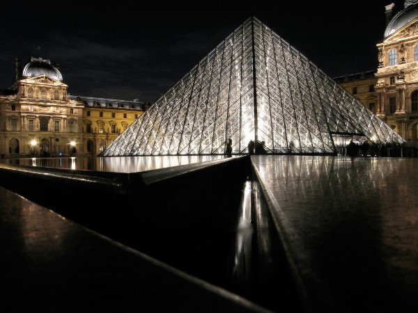
The Louvre Pyramid

louvre-pyramid_1

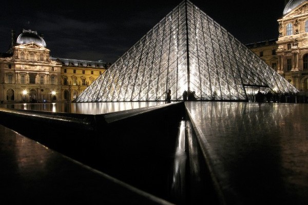
French president François Mitterrand, in 1984, appointed architect I.M. Pei to design & construct a new entrance for the iconic Louvre museum.  The Louvre Pyramid was the outcome, one of the well-known works of glass architecture till date.  This great glass pyramid grows out of the square in front of the Louvre at an altitude of 70 feet, comprising of 673 glass sections from base to tip.  Visitors arrive the pyramid to descend below-ground afore ascending again into the main level of the museum.  While the Louvre Pyramid was built in the middle of much critique & controversy, it has been praised by architecture fans as a well-executed merging of modernist & classical architectures.

Visit Us: StrucCore.com

Jdombs-Travels-Burj-Khalifa-2

Facts About Burj Khalifa You Should Know

Jdombs-Travels-Burj-Khalifa-2

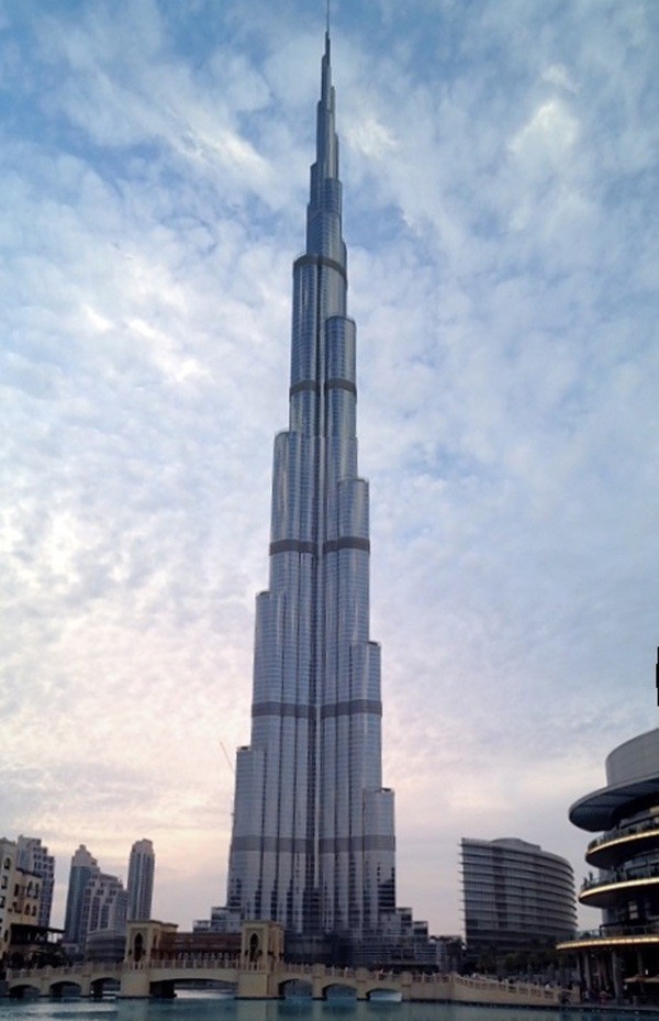
  1. The Burj Khalifa stances at 828 meters (2,716.5 feet) tall, rising over Dubai. It’s nearly twice as high as the Empire State Building and three times as high as the Eiffel Tower. Laid end to end, it sections stretch over a quarter of the way round the world.
  2. Apart from being the tallest building in the world, Burj Khalifa has six other World Records:
  • Highest number of stories in the world,
  • Tallest freestanding structure in the world,
  • Highest outdoor observation deck in the world,
  • Highest occupied floor in the world,
  • Tallest service elevator in the world, and
  • Elevator with longest travel distance in the world.
  1. The total load of aluminum used on Burj Khalifa is comparable to that of five A380 aircraft. The mass of the concrete is the same to 100,000 elephants.
  2. Each year 15 million gallons of water are collected sustainably.
  3. It has the lengthiest single running elevator, with 140 levels. The elevators are among the fastest in the world and go 10 meters per second.
  4. The peak of the sphere of the Burj Khalifa can be seen up to 95 kms far.
  5. 12,000 workers were employed on the building per day, at the peak of construction.
  6. It took more than 22 million man-hours, 110,000 tons of concrete, and 55,000 tons of steel rebar to complete the giant building.
  7. Excavation began in January 2004. The Burj Khalifa finally opened in January 2010, six years later.
  8. Burj Khalifa is intended to bear a resemblance to the Hymenocallis flower; the central core appears at the top and concludes in a sculpted spire.